Saturday 24 October 2015

Build Day 9- Prop Shaft, LSD, Radiator


Day 9- Prop Shaft, Clutch Hose, Limited Slip Differential and Radiator.

Cut Down Allen Key

To start off we, incredibly slowly, engineered the cut down Allen key needed for the gearbox filler plug, and also then found a use for the excess end. On our Duratec engine in our SV model there are 3/8" bolts going through the engine mounting arms and into the rubber mounts. As most people will also find there isn't a 3/8" Allen socket adaptor in any regular set without getting a completely separate set, so we used the excess end in a 3/8" socket to be able to adequately torque the engine bolts, which we immediately did.   
A good 30+ mins taking a hacksaw to this key...


Parts together ready for torquing.

Prop Shaft

This has got to have been the most frustrating thing so far... 
We slid the prop shaft in through the back and aligned in in the tunnel ready to connect it to the engine. After coating it with copper grease as required, me under the car and dad lifting from the top, we attempted to align the splines and connect the shaft. However after a short while of struggling we were still unsuccessful. 


From my perspective I thought the problem could've been that the gearbox shaft was turning, so we decided to install the gear stick so we can then lock the gearbox to stop the shaft in place. However after an hour of guessing how to attach the gear stick we eventually back to aligning the shaft, which was still to no avail. Up to this point we had been giving Caterham the benefit of the doubt as to have given us the correct part, but it eventually cracked and we measured the two parts with a pair of vernier calipers, only to find a 1.5 mm difference between the two. At this point we decided we had waisted enough time trying to establish whether it was the wrong part or whether I suck at using calipers and added it to the extensive list of things to try and get Caterham to clarify... 


We sent a pic of the shaft label to email for verification.

Clutch Cable

To de-stress for a little bit we decided to quickly fit the clutch hose to the clutch reservoir. There is already a connection in the top of the reservoir, however the connection already fitted through the banjo joint so we simply removed the quite purposeful looking part and connected the hose.  


Removal of fitted connection.

Actual connection method for the clutch hose.

To stop the hose being damaged on the edge of the pedal box we wrapped it with self amalgamating tape.

Radiator

Thus far with the radiator we have found that the slots in the side are too short and small to be able to get it over the roll bar and then have enough clearance to get the bobbins between the brackets and the cowling. The only help so far has been to refer to images of how its make in the factory, which clearly shows the hey hole shape cut into the cowling; and that Caterham themselves cut the slots, thus only raising the question of whether we have the right cowling or not, again... 

In the end we have decided to just remedy the situation our own way. We decided to use an old tool of my father's father, called a Lang/ Turner Nibbler, a device which cuts sheet metals of different thicknesses.
Nibbler, Just found it on Amazon for £85... glad we had one.


Just the promo video of the nibbler showing its capabilities. 

Marking out a small section, initial mocking up seemed quite close.

However first alteration not quite there yet...

Still only one side can be positioned.

Second alteration, making it look slightly more like the standard key hole shape.

Third alteration, gave in trying to make it a close fit and just made it look as similar to the factory version as possible. 

Finally all tightened up with, as always, a plain washer between the spring washers and the metal surface.

Summary shot of the car so far!!!

As I have written this a few days (Tuesday) after  actually completing this Derek has helpfully sent us the correct prop shaft which arrived earlier this evening. It is currently sitting in its box next to the even larger box containing the correct tunnel top. We can't help but estimate hundreds of pounds have been spent by Caterham getting these parts (plus others) to us in the post or by courier on next day delivery.

Tuesday 20 October 2015

Build Day 8- Trying to fit Radiator

Day 8- Trying and Failing to Fit Radiator

During the day, while dad was at work I had tasked myself to spend an hour or two to tidy and fitting the radiator brackets, fan, cowling and the radiator. To start I screwed the fan to the back of the radiator cowling with the power cable on the right hand side of the car. Then I slid it behind the front ARB and loosely attached the brackets. I then proceeded to try and get the radiator cowling in front of the brackets and then far enough past it to get a 70mm long bobbin which in my eyes was completely impossible without completely bending the cowling out of shape and have the ARB rubbing against the back of the cowling. 

Last week we had read through the radiator section of the manual to find all it says is that the SV radiator fitment is very different to the S3, and that the R400 (being used for 420 instructions) radiator fitment is very different. However it doesn't go into much detail into either and especially doesn't go into any detail into ow they are combined to build the radiator on our car... so we emailed Derek to ask how the hell this is done. He replied with some photos of a factory built 420 SV car.

RHS roll bar passing through the radiator cowling and behind the radiator bracket. 


Our Radiator Cowling.
Comparing the two cowlings it is easy to see why ours doesn't fit, as the one in the factory has a large key hole shape cut into it, whereas ours just has a shallower slot cut into it. At this point I decided to give up and go and ask Derek if we have the right cowling (AGAIN as we had previously asked as the cowling has "Sigma Radiator Cowling" Printed on it). 

I am also unable to find the covers for the holes in the back of the radiator cowling, which also seem to be different through others' online blogs and from the images sent by Derek, so we will be asking about that too. 

Monday 19 October 2015

Build Day 7- Front Anti Roll Bar

Day 7- Front Anti Roll Bar

It's a Monday Evening so we aren't going to do very much, so we have decided to get the front anti-roll bar in. Firstly the manual says to install the radiator inner cowling before the ARB, however in our eyes, and we have tested it, the cowling will go in after so we will ignore the instruction.

First the rubber bushes had to go into the brackets, some silicone spray was helpful in doing this. These were then slid onto the ARB, then the rubber boots were slid on and the plastic balls were tightened on the end of the bar with protected pipe grips. We then coated the ends on the balls with grease and put some into the cups, which turned out to be too much, as it hydraulically locked the cup causing the brackets to stand off to far to be tightened. We then removed the bar, removed a little grease (and a lot of paint which scraped off as the ball went in) then re-positioned the bar. This is actually not too hard, one person is enough (possibly made easier by the longer bar on theSV model), then torqued adequately. 


A dab of grease coating the ARB ends.

Just a quick but of de-burring of the radiator brackets.

Sunday 18 October 2015

Build Day 6- Gearbox Filling and Engine In

Day 6- ENGINE IN!!!


Gearbox Oil


First off we decided to fill the gearbox before sticking the engine in as we aren't concerned with weight due to the two ton lifting capacity of the engine hoist. 

However, first problem of the day:

  • We do not have a 3/8" Allen key.
Second problem:
  • We have only been supplied with 1Ltr of gearbox oil and 1Ltr of Diff oil. 
So, off to B&Q for a cheap imperial Allen key set and the local car shop for some more GL-4. However when it came to buying more oil the shop didnt have any GL-4 in stock, so we improvised and went for some GL-5 instead, as the manual and owners manual both state that both are suitable in their gearboxes. After my dad did some research after we finished tonight it turns out that previous owners have pondered the same but have been told by Caterham, when asked, that only the GL-4 is suitable and the manual and the handbook would be updated... (or not)

In light of this we have come to the conclusion that it will not do any damage and we will be changing all the oil after the 500 mile run in anyway.  

Much easier before it's in...
Gearbox levelled off and filled until dripping out the hole. 

Rubber foot attached before lowering in.

Engine In


First we dragged the engine on the pallet over to the front of the car and aligned it with the hoist. After creating a strop and adjusting the lengths to roughly get a 40 degree angle on the engine, we bubble wrapped the gearbox to protect the chassis tubes while trying to fit such an immense engine and gearbox into such a small space. Also, as instructed, the long "L" shaped hose onto the back of the engine, a bit fiddly as the 40mm jubilee clip is not big enough to slide on while it has bitten. We remedied this by clamping it with some pipe grips then tightening with the driver.   

Wrapping the gearbox.

Unease as it is slowly lifted. 

At this point we were still optimistic about it being able to fit without any engine modification.
Beforehand we also added extra protection along the engine bay and around the tunnel to protect the heat shielding and chassis tubes.

The manual states to remove alternator, remove starter motor, and fit the long "L" shaped hose. Our advise (for Duratec engines on SV model at least) is to NOT fit the hose as it interferes with the wiring loom; do NOT remove starter motor; REMOVE alternator; REMOVE right hand engine mount. The alternator is easier than some might think, as there is a self tensioning pulley at the top, and two bolts top and bottom of the alternator.

In the end we admitted defeat and raised the engine slightly to modify things.
Alternator  unbolted and cable tied to plenum chamber.

Much easier now without mount and hose.
Once the gearbox was nearly in position we put the trolley jack under the car to lift the gearbox and also allowing for a higher and further pivot point, allowing for the engine to lower and not the gearbox.  

Trolley jack under rubber foot. We had previously packed the cup on the jack with layers of silicone to protect the paint on the chassis.
Once the gearbox foot aligned with the bolt holes for the bracket we loosely bolted it in place so we could get the jack out of the way and fully align the engine mounts.

Lowering Gearbox onto bracket.
Once the foot was in place we lowered the engine into position over the rubber engine mounts we reattached the RH engine mount bracket and through bolted them in place.


Engine roughly in place with L hose back in place (albeit the wrong place, which only emphasises the point of, "why the hell are we asked to put it in beforehand"). 

Mount re torqued to block.

Possibly overkill for the hoist, but very handy.

Touching on RH side of bellhousing and LH starter motor. These both do not allow for any more adjustment either way without damaging the heat shielding. Will ask Derek for advise as to how they align the engine.

Bracket and foot torqued. Foot to bracket bolts left for later when adjusting alignment.

View down the underside to finish the night. Also we had to lower the front off of our handmade rolling axle stands due to the stands being too wide to fit the hoist around it and too low to fit the hoist under it.


Saturday 17 October 2015

Build Day 5- Gear Box and Bits

Day 5- Gearbox and Bits

Washer Bottle

First off we ran the windscreen washer tube into position before the engine and gearbox can fill the tunnel. We just lowered the tube down through the top of the tunnel and through the seal, then loosely cable tied the hose to the wiring loom, then tucked it in behind the passenger foot well ready for the washer bottle fitment. 

Wiring loom up through tunnel. Heater not plugged in yet as it seems impossible to find the plug without lying upside down in the foot well...
Washer bottle in for dry run, has  to be put in after the engine fitment as the mounts can't get passed otherwise.

Horn

As we have the dry sump system as standard in our car the normal horn mounts are not used due to the dry sump tank being in its place. An 8mm hole has to be drilled through the steering rack platform, which we then painted with metal paint. We then realised that it didn't matter whether the paint had dried or not as we didn't have the metal spacer or the right nut and bolt for its fitment anyway. 
Hole off centre in order to not weaken the mounting. 

Hammerite Metal paint.

Rust Protection

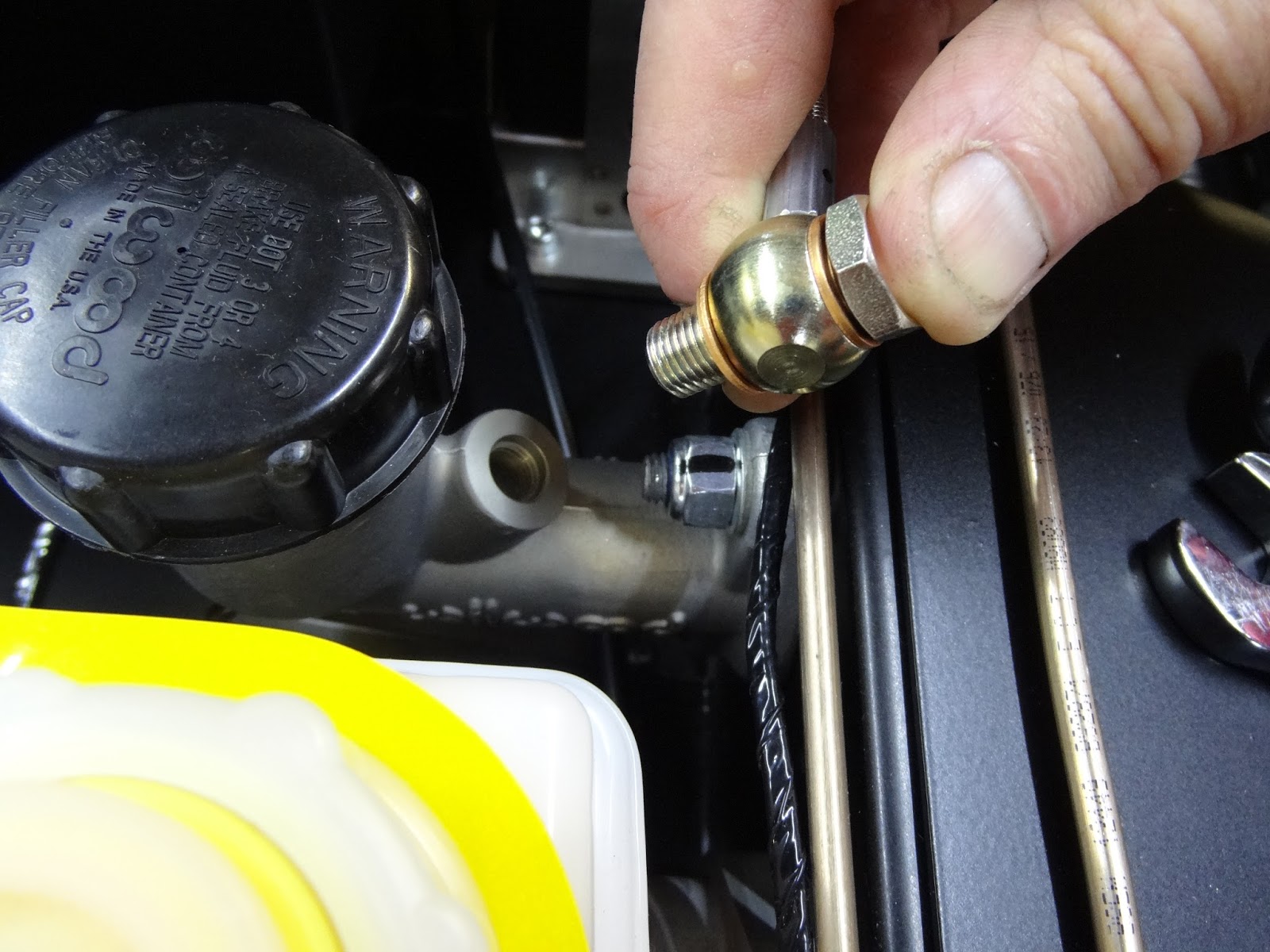
After reviewing some of the images we took during our visit to the Caterham showroom, we noticed that one of the cars had a few rusty parts in the engine bay. We decided to remove the throttle cable mount and give it a lick of paint. 

Rusted parts on a second hand Caterham.

Gearbox Attachment 

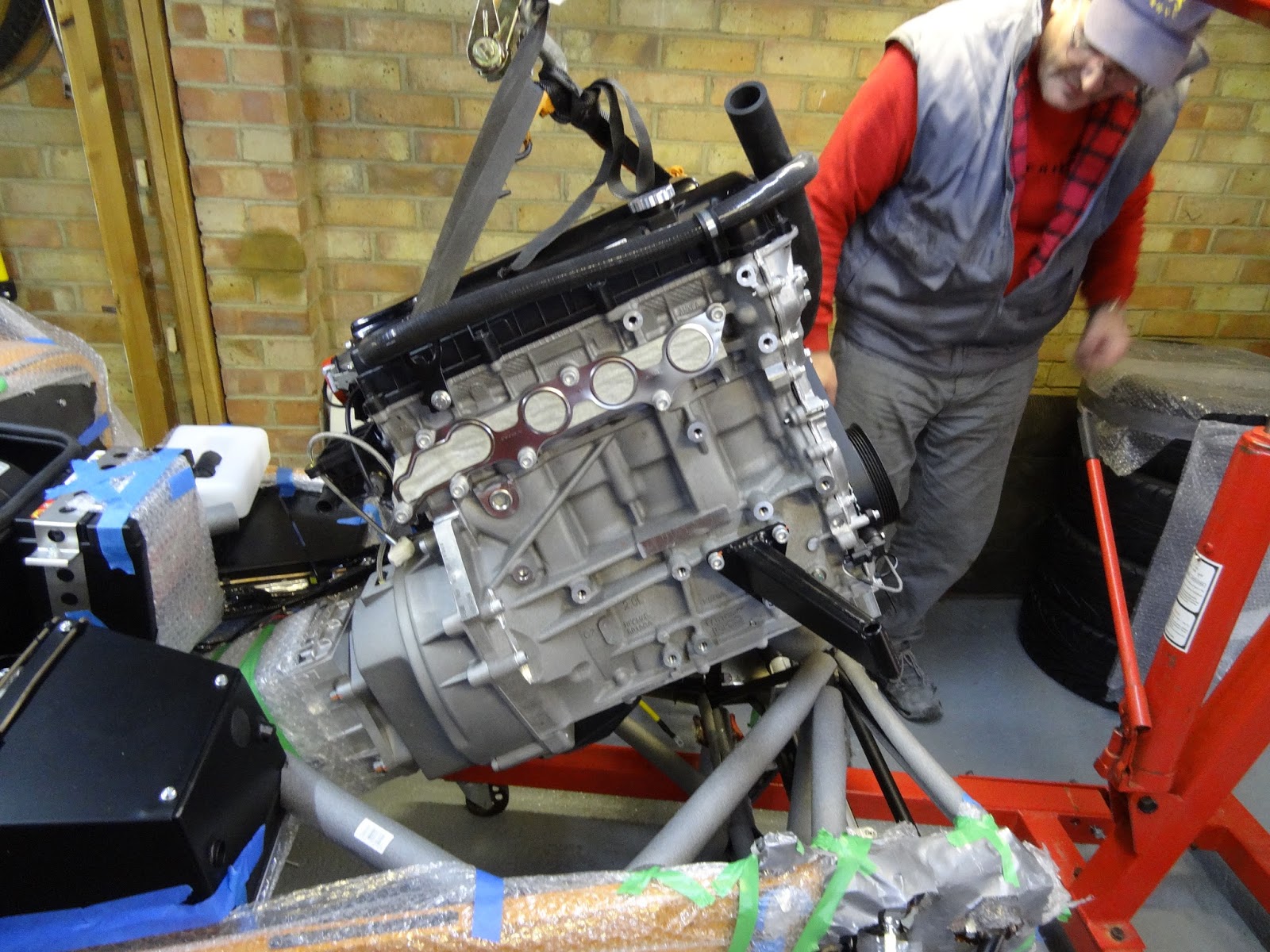
Naturally reading the instructions on how to attach which gearbox to which engine, to remove or not to remove bell housing, to plug or not to plug...

In the end we asked Derek who confirmed that on the DURATEC, with a 6 SPEED GEARBOX, the bell housing is left on and the gearbox is bolted to the bell housing. This was done with no gasket (not supplied and not required) and no silicon was used. 

We then plugged the LH speedo hole sealing with silicone sealant, and then sealed the Rh speedo output hole at the base of the box with the plug supplied and using gasket sealant. The gearbox was then relatively easy to bolt on, apart from until we got the the torquing up, which was near impossible due to the clearance around the bold heads not allowing the socket and torque wrench near it.  
  
How the hell is this going to fit!?!?!?!?!?

Engine Mounts

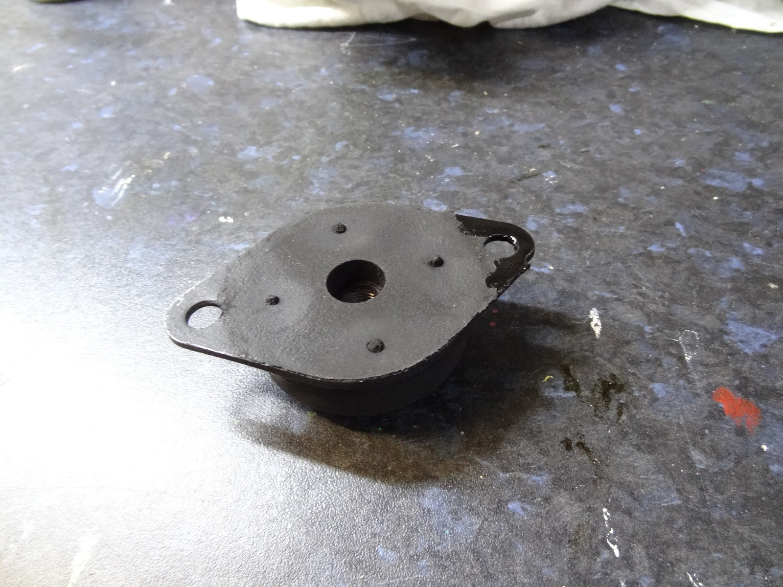
We decided to finish the night with rubber feet which the engine sits on. First we had to clean up one of the ends around the forward hole, top and bottom, then on the frame. This was in order to allow a sufficient earth connection for the engine. Then on the RH rubber mount we had to file down the trailing outside edge as it was fouling on the chassis tubing welds, it was then painted and allowed to dry for fitment next time. As instructed the mounts were loose fitted in order to allow for engine alignment later.

LH mount with 300mm Earth cable.

Finely tuned RH mount.


Monday 12 October 2015

Build Day 4- Front Brakes & Heater

Day 4- Front Brakes and Heater

Thanks to Derek for his quick reply with some pics, shown below, we were able to fit the front brake hoses tonight with the use of the photos he helpfully sent. So as I cooked dinner dad finished the job.
Hose to calliper 
Hose through body
Brake line connection

Heater Fitment

After dinner we decided to quickly fit the heater. This was very simple and I can imagine was made much easier by having two of us. We started with the sealant around the edge, then slotted it into place ensuring the cable was through the vent holes then put the vent face plate into place, passing the bolts through.
Thin bead of silicon around the edge of the heater panel

After the panel is in place more silicone is run along and around the edges to ensure no water is able to run through
When the vent plate goes on make sure the ducts for diverting air down towards your feet, or "Horns" as they seem to be called, are downwards, which is the other way up than it arrives.

Sunday 11 October 2015

Build Day 3- Front End

Day 3- Front Suspension and Front Brakes

Today we aspired to finish the front suspension, however this didn't happen as it was a lot more fiddly than we first thought.

First we sprayed some Dynax inside of the De Dion tube.
Coats well but goes everywhere...
Naturally can't work while ignoring the F1
We then continued to finish the upper and lower wishbones. This continued to be a little fiddly, however with a little persuasion (with a mallet) they slid into place and were bolted as per the manual.

We then moved onto mounting the front disks. As these were the ventilated disks and quad piston callipers they lower right in and do not require to be built. We soon found that it would be impossible to have the top and bottom wishbones bolted to the brake uprights and then tighten the special milled nyloc on the underside of the lower wishbone. This was due to there not being enough clearance for any of our sockets to fit on properly. To fix this we disconnected the top wishbone from the upright then tightened the nyloc to the required torque, but to get enough leverage for the torque setting, the disk had to be secured. We did this by clamping two lengths of wood either side of the disk.
Wood in place
After this the top wishbone was attached and all of the nuts tightened to the required torque settings.
The angle of the bottom upright can be seen here. All bolts torqued and marked.
Cycle wingstay fitted to centre of the upright.
Premier Digital Torque Adaptor, can be used to test accuracy of existing torque wrenches or used as a torque wrench itself with a socket set and drivers.
Dad trying to work it... instructions are worse than the build manual...

Just a quick bit of lunch then back to finish the left side of the front suspension.
Finally the finished front suspension
Just a little free time for dad to quickly pose for the camera...


Annoyingly the GoPro ran out of battery without us realising so only the first half of the day.
To finish off the night we decided to fit the brake lines, which proved to be a bit too much today... This was all due to the brake hoses being completely different to the ones shown in the manual. The fittings are not the same and there are fewer parts supplied than described. This discovered we decided to to call it a night and email Derek for help and to enquire as to why the grill in the nose cone had not been painted, despite being, sold, bought and paid for.