Sunday 29 November 2015

Build Day 26- Headlights


Day 26- Fitting Headlights 


Headlights


In order to fit these we started by removing the forward, front, top wishbone bolts in order to get the light bracket on. Then we attached the indicators to the pods, which had previously been trimmed in the IVA trim. 


Fingers not small enough to get the top nut on.
We then replaced the protective tubing on the indicator and light wiring with heat shrink as it is easier to feed it through the bracket. Then the all the parts were fitted to the bracket making sure to put it together the right way, which we only did after the third time building one. Previously Dad had put a new length of green wire going from the inside of the headlamp bowl and to the length of the rest of the wires. This allowed us to earth the indicators to the bowls and power them as normal giving better aesthetics. 

Earthed to bowl and indicator green connected to dark green automotive cable. The pin connectors were removed with a length of cable, which was then connected to the end of the darker green cable.
First the wires are fed through the grommet in the body, then the bracket is fitted.

This is much easier than trying to feed the two wire protectors through, which don't shrink.

The carbon parts look great, such a shame the carbon bowls (available from Westermann Motorsport) are over £700 for the pair, which will have to be a later mod. However the pods will do which were only £28 a pair, but have since gone up to £45 on demon tweaks.

Not hugely tidy on the other end at the moment but we'll tidy that later on when the wing indicators are fitted.


Saturday 28 November 2015

Build Day 25- Side Screens, Knee Trim, and Sill Protectors.

Day 25- Side Screens, Knee Trim, and Sill Protectors.


While I had been away on my oil Tanker Course dad had been fiddling and had managed to wrap our  

Side Screens

First we attached the hinges onto the windscreen using the black bolts, black domed nuts, black washers and some loctite to hold it together. (On this part be careful with the bolts as the heads are very easy to gouge out with allen keys so use minimal hand torquing) Then we put masking tape down the leading edge of the RH side screen, lined the screen up with the hinges and marked the drill holes with a pen. This is tricky as the holes comes very close to the edge of the internal metal frame, when trying to get the back of the screen to align concentrically with the rear wing. 


Aligning the side screen.


Cleaning out the screen.

After drilling the holes we cleaned out the swarf, with a paper clip, from under the vinyl exterior. Finally we gingerly attached the rest of the hinges to the door and fitted it to the car.  

We then intended to move onto the other door, however when we unwrapped the other screen we discovered that it was a scuffed second hand one that had been drilled already. We will have to get Caterham to send us a new one as soon as possible. The second hand one can go onto the pile of things that are going back to Caterham at the post build inspection.

Knee Trim and Sill Protectors

Before any of the interior panels can be riveted the sill protectors and the knee trim panels have to be fitted. We started at the front and worked our way backwards, firstly by inserting the knee panels then marking the holes as the pre drilled ones, as all have discovered, are nowhere near being in the right place.

Panel holes centred and clamped ready for drilling. 

When going to fit the panels we decided to fit them using self tappers instead of rivets so we would later have the opportunity to remove the windscreen if and when we buy an aeroscreen.

Tappers in and rubber trim sandwiched in-between the body and the side panels.

We continued to put the self tapping screws in until they reached adjacent to the scuttle edge, then moved onto fitting the carbon sill protectors. First we ran a length of masking tape along the bottom edge of the deeper side of the protector. Then held it in place with the front edge in line with the rear corner of the scuttle, and marked the holes for drilling. After drilling the holes we did the same with the armrest catch having aligned it with armrest pin. 

Surprisingly tough to drill these little bits of stainless.
Sill in and looking great, thankfully we remembered to fit the rubber trim. To fit the rubber trim we drilled holes through in transit so as to guarantee the tautness of the trim.  


Riveting finished. As we don't have the other screen we can't move on to the other side.

Speed Sensor

While Dad finished the riveting I decided to fit the speed sensor. In order to protect the cable we covered it with heat shrink, then installed it in the bracket. Hopefully it will work properly as others have had trouble with it in the past. 

Shrinking to fit.

Hopefully this is enough gap between the sensor.

Heater Hoses

To finish the evening we had a quick tinker with the layout of the hoses as there are many things that restrict the layout.


The 'J' Hose on the right had to go over the top and pinned thus otherwise the shape would kink thus restricting flow. The submarine T piece has to go upside down due to the long end of the T piece not fitting inside the P-clip, and because the earthing lead not being long enough to actually reach the lug anywhere else. The P clips are just being used in order to remove kinks. This is made worse by the fact that trying to get the T piece any close puts a kink in the hose coming from the heater control valve, no matter how we arrange the hoses.    


Sunday 22 November 2015

Build Day 24- Left Rear Wing

Day 24- Left Rear Wing


Another lovely day to be working in the garage...

Left Rear Wing

We started the evening the same way as we started fitting the right wing, that was, until when loosely fitting the wing we discovered that the forward most rivnut was turning in the chassis. Therefore we had to remove all of the bolts in so far and then try and remove the bolt from the rivnut in order to see what we could do.

Making room for getting the bolt off.
Dad then used a drill bit to hammer a notch into the lip of the rivnut in order to be able to stop it from rotating while I remove the bolt.

Trying to stop the rotation.
This method ended up being successfull meaning we could carry on with the original procedure but with the added complication of the front bolt being slightly harder to tighten after. In the end the front bolt went in, possibly not as tight as we'd like, but it was in.

Finally on.


Saturday 21 November 2015

Build Day 23- Tunnel Plate and Right Rear Wing

Day 23- Tunnel Cover and Right Rear Wing


Tunnel Cover

First we ran a bead of silicone along the top of the tunnel tubes, then aligned all of the rivets and proceeded to pull all the rivets from rear to front.

Absolutely freezing!!! 2 jumpers, boiler suit, jacket, and hat much needed.
Someone's little joke on dad.

We then put a bead around the edges to seal the holes and neaten it up.

Rear Wing

In order to get the wing on the car the link arms had to be removed, which we decided to do instead of cutting the large slot out of the wing. Then we loosely attached the right wing, then cut a piece of trimming roughly to length and started trimming it to fit. Firstly we punched a hole in the end for the bottom rear hole. Then while pulling tight we marked and cut slots for the bolts to pass through, and then large slots to remove slack in the rubber.

First hole. Metal punch set used a few times so far, pretty useful in this.

Small "V" for small bolts, Square for the Link arm mounts, and deep "V" cuts to allow it to pass around a smaller radius.

Finished Trim.

Before tightening the wing we had to re-fit the link arms as the play in the wing is required to allow the radius arms to swing back into place. It was at this point that we realised that the holes in the rear wing for the link arm bolts to pass through weren't quite in the exact place for the washers to not foul. To fix this we took the arms back off and removed the front bolts, which gave enough movement to be able to get the Dremel in to widen the hole. 

Widening the hole.

Now there is enough clearance for the washers to fit in the hole and not have the wing ride on top. Plus no need to cut a large slot in the wing.

To finish we started with the bottom rear bolt, so while one of us pulled the trim taught and held the wing in, while the other tightened the bolts, continuing round the wing. 

Action shot to prove it is us building the car and not pros. We are getting good at sleep building though.

Finished trim.


Friday 20 November 2015

Build Day 22- Handbrake, Breather Hose Bracket, and Engine Earth.

Day 22- Handbrake, Breather Hose Bracket, and Engine Earth.


Handbrake

To get the eye of the handbrake cable onto the hook on the top of the calliper, as much slack as possible has to be taken out of the adjuster in order to have enough length to get the eye onto the hook. 

Handbrake cable connected.

Oil Breather Hose Bracket

We felt that the oil breather hose running from the top of the engine and the top of the sump tank felt unsupported, so, to remedy this, we made a bracket out of an old aluminium sheet in the garage.

Using the reciprocating saw to cut the strip needed for the bracket. This has been used a worrying amount during this build, an invaluable piece of kit.
Bent and in position. After we will clean it up and add some self amalgamating tape around the sides to reduce chafing. 

Engine Earth


While dad was making the bracket I was having a tidy and attaching the earth strap to the engine. One of the Bellhousing bolts is removed then passed through the larger eye of the black battery lead, then re torqued.

Negative battery lead in place.

Wednesday 18 November 2015

Build Day 21- Sump Tank Plug and Watts Linkage

Day 21- Sump Tank Plug and Watts Linkage


Sump Tank Plug

Bought some copper washers from the local car shop and fixed our hole problem.
   
Bolt, spring washer, plain washer, and copper washer.

Watts Linkage

After going to fit the rear wings we found that it is easier to fit the wings first then the watts linkage (or radius arms if not opted), this way a slot doesn't have to be cut out of the wing, the hole may only have to be widened. 

First we attached the rod ends to the link arms, measured to 475mm and 244mm centre to centre of the rod ends, then tightened the rod end using the locking nut. 

Dab of Loctite under the locking nut.

The link rod ends are then inserted into the bellcrank after the bell crank is widened to fit the rod ends. The rod ends are attached with the small bolts ensuring that the locnuts are on the same side as the raised side of the bellcrank, and that the waisted sides of the link arms are on the appropriate side.

Through Bolts for chassis attachment. Plenty of copper slip used.
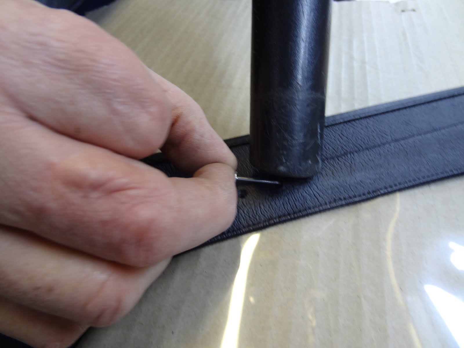
In order for the bellcrank to fit into the di dion tube the brackets had to be widened. We did this using a rag covered crowbar. The bellcrank spacers are then pushed into position inside the brackets (convert the 1/2"  holes to 10mm holes for the bolts to be seated). The bellcrank is inserted and then bolts threaded through.

Bellcrank in bracket.

The link arms are then bolted to the chassis using appropriate bolts and washers, then torqued to required value. To get the arms to align properly the di dion tube has to be lifted slightly to align holes. This is where two pairs of hands comes in handy.

We followed this method as we found that if following the instructions (link arm on first, then torqueing the arms when parallel to the ground, then attaching bellcrank) the link arms just rotate when moved into position for the bellcrank, meaning that there is not much value in the arm being spring loaded. 

Right hand side in.

Tuesday 17 November 2015

Build Day 20- Dry Sump Hoses

Day 20-  Dry Sump Hoses


Hoses

This part was quite tricky and took quite a long time to finish. This was mainly due to the hoses being very tight for length, and that the angled neck of each hose only allows it go certain ways to travel from the cooler to the tank. Hoses join:

  • The LHS of the cooler to sump tank top.
  • The RHS of the cooler to engine out.
  • The bottom connection of the sump tank goes to the engine sump in.
We found that the connections with smaller diameter necks went onto the engine connections, the medium right angle connections went onto the underside of the oil cooler, and the larger necked connections went onto the sump tank connections.

The hoses don't reach from the oil cooler to their destination if the instructions are followed (possibly only for SV cars), as they are not long enough to go along the bottom of the radiator and around the LHS of the radiator.

The RHS - engine out hose runs under the radiator, under the steering rack, under the diagonal chassis tube, and onto the connection.
The short hose from the bottom of the sump tank to the sump connection, goes straight on, just making sure it doesn't foul on anything.

The top sump tank hose tuns straight down, under the radiator and straight onto the LHS of the oil cooler. 
A lot of care has to be taken to ensure that the blue threaded heads aren't cross threaded, as they are very easy to damage due to them being aluminium. 

Before finishing we noticed that we hadn't done anything with the large hole in the front of the sump tank. However there weren't any instructions even mentioning it, so we found an appropriately sized bolt then planned to buy some copper washers in order to be able to adequately seal the hole.

Hole in front left of tank??? Not a drain hole as there is one in the underside...


Monday 16 November 2015

Build Day 19- Droplinks, Heater Hoses, Engine Electrics, and Oil Cooler.

Day 19-  Droplinks, Heater Hoses, Engine Electrics, and Oil Cooler. 


This time of year it is starting to get very cold in the garage. Working with tools at 5 degrees is getting tough, so we bought a fan heater to try and make working on the car more bearable.

SO MUCH BETTER!!!!


Droplinks

No we knew that the droplinks aren't put in how they're instructed to, we could now put them in. The instructions say to find the links in as far as they go down, but with the threaded ends in the same direections... but what it should say is, "threaded ends in opposing directions". Then ignore the part about the extension pieces and just bolt each end through the bracket and the ARB. The further up the towards the rubber bobbin the less roll with be experienced.


Engine Electrics

Now we've done more research we know think we have sorted the wiring issue. Still however dad was the one under the car so either he can elaborate or the pictures will have to do. 


The four connections from the previous post, unused, so they were just taped together with self amalgamating tape and cable tied to the engine mount. 

Oil Cooler

Started by assembling the brackets to the cooler unit. We used our own nuts and bolts as we couldn't find any suitable enough, so a bolt, locnut and two washers either side of the bracket, for each hole. 

Assembled off the car then used to mark up the right holes to be drilled in the cowling and radiator brackets.

We made sure all of the aluminium was pushed in-line with the other parts as the cowling is very thin and the edges are all over then place. 

Once we were happy with the hole placement we drilled the 8mm through the aluminium, then bolted the oil cooler to the cowling. The top hole uses an M8 bolt and the bottom hole goes onto the bottom radiator bobbins.

The fitted cooler.