Day 15- 'A' Frame, Steering and Rear Brakes
'A' Frame
More prep for the weekend, so started with the A frame. I didn't want to fully fit it until dad got to have a say on it so I just loosely fitted it with roughly the right washers, the correct bolts in the front two mounts, and the correct bolt and nylon washers through the di dion tube. Just remember to tighten the A frame to the di dion tube before trying to centralise the A frame using the di dion tube, otherwise it will throw the tube out of alignment.
Rear Callipers and Brakes
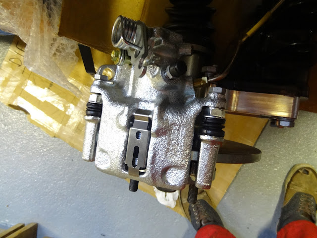
I then moved onto the rear calliper assembly. Firstly by sliding the disk over the splined end of the drive shaft, then putting the hub nut back. Following this the calliper brackets can be bolted onto the tube ears using the bolts used previously. The brake pads are then placed into the recessed slots either side of the calliper brackets.
Before the callipers are bolted on the retaining clip must be slotted into the rectangular hole in the top of the calliper. We had found that attaching the brake line first to get the right alignment for the thread, then lowering the calliper into position and bolting it on, was the best way to fit the calliper, otherwise the brake line seems too easy to cross thread and it would be hard to get the perfect bend on the brake hose otherwise.
 |
| Fitted calipers with clip in top. |
Steering
The steering was fairly easy to put in, but couldn't be finished as we haven't finished cleaning and polishing the primaries, the cat, and the exhaust. The lower column went in first, just slid up through the two rubber grommets in the foot box, which was made easier by removing the covering plate. Then the upper column is slid down through, from the top, making sure not to dislodge the white plastic liner of the rubber bushes. The upper bush can be slid onto the upper column before or after, depending if a QR steering wheel has be opted for.
 |
| Column clamp left loose for completion later. |
I then loosely fitted the clamp to the middle of the column where the two meet, with the edges aligned. Moving onto the universal joint, between the steering rack and the steering column, it was evident that the job wasn't going to be completed due also to the front uprights looking considerably toe out, meaning that the track rod ends were going to have to be taken off and that the number if turns given in the instructions is wrong. I also found that the bolts passing through the universal joint and stopping it from pulling off wouldn't easily go through (only on the steering rack end) so the joint had to be opened up a little.
 |
| Left like this until the primaries are fitted. |
Later on we will finish this job once the exhaust is completed. This will hopefully resolve the wheel alignment (turns on the track rod ends) and also how much tilt is required on the steering rack, as we are unsure as to whether the steering column will foul on the primaries if the rack is at certain angles. We would prefer this to be as in line with the steering column as possible.

No comments:
Post a Comment