Having finally had the chance to have a look around under the bonnet and nose cone we've been able to find a few things that Caterham have carried out over the last week. Here are a few things that may help others who are building their car, and a few things that are the up-to-date how-to's for building the car ready for VOSA.
One job that we were going to do, but ran out of time, was to bend the wipers so they are parallel with the windscreen, which Caterham have done for us.
Caterham have added another negative lead to the battery, which then bolts to the chassis under the heater control valve.
Extra lead. Also the battery breather hose had also been removed.
The Battery covers have been changed and removed.
When looking at the oil breather bottle we noticed that they had removed the breather hose, and had removed the hose clips holding the breather bottle hose.
The breather hose we had relocated has temporarily been plugged to stop dirt getting in and allowing us to later fit another cover or hose.
Admittedly we made a little bit of a mess with the wiring for the right hand headlight, which was functional but not pretty, however it has been moved from under the expansion bottle and onto the chassis tube. Also the indicator earth we had sliced into the headlight assembly had been removed and bolted to the chassis in the same way as we had done on the LHS.
We can't remember whether this hole behind the brake line was there before, but we can't imagine someone would drill a new hole into a chassis tube. Also, as can be seen here, the trim around the exit hole for the steering arms have been removed.
The braided clutch cable had a length of fuel hose over it in order to protect it. No idea how this has been put on, unless it has been cut open and cable tied, as I didn't check.
The front edge of the cat guard has had a small length of scuttle trim added.
The way the handbrake cable has been fixed to the 'A' frame has also been changed. Before we used 'P' clips to hold it off of the drive shafts and the chassis, as others have done, however now it is being held in place with cable ties.
Cable ties around the rubber sleeve pre-attached to the cable, and onto the 'A' frame.
The length above the diff has been held off by a cable tie.
Another length of fuel hose has been used to protect the brake hose to the rear brakes.
All of our cut down seat bolts have been removed and replaced with the original length of bolts...
For the life of us we cannot unearth what they have done for the quoted two hours removing and re-attaching the Di-Dion ears.
Just no idea...
The engine seems to be working fine, sounding like it should, and now all of the exhaust it the correct colour.
A piece of scuttle trim has been fixed to the underside of the steering rack bridge in order to reduce abrasion to the oil hoses.
From Above.
From the front.
To end the day we decided to add one of the last visual finishing touches to the car by adding the recently acquired nose badge. We decided to go for the black and chrome Super 7 badge sold by Caterham, as the rectangular green monstrosity isn't going to go well with the colour scheme. The dilemma of the badge seems to have been resolved by Caterham as, according to an article in Low Flying, the badge has been changed to a black circular design, which is currently on the 620R and 620S.
By drilling through and bolting the badge to the nose cone we don't have to worry about the self adhesive patch, on the back of the standard badge, sticking to the paint protection film.
The black badge surround is very similar to the "Starlight Black" stripe.
Day 35- Throttle Cable, Brake and Clutch Bleeding, and Reg Plate Light
Throttle Cable
We have decided not to do as instructed and bend the throttle pedal, and follow the advice of my Cousin, who used to work for Arch Motors constructing Caterham chassis' and has since worked on many Caterham rebuilds and repairs. His advice, as he had done this many times, was to remove the plastic from a chocolate block connector and and clamp the metal clam to the throttle cable either side of the pedal.
We cut the end off, passed it through the hole, then connected one block before then two after.
Brake Bleeding
This is fairly easy but time consuming, and requires 2 people, unless one has an Eezibleed kit. Did this as instructed in the order:
Left Rear
Right Rear
Left Front, Inside
Left Front, Outside
Right Front, Inside
Right Front, Outside
This was going well until we managed to get air in the system from not topping up the fluid regularly enough. We did find that taking a rubber mallet to the callipers did wonders for dislodging pockets of are trapped in parts of the calliper. This was all going to plan up until the third circuit, where we ran out of fluid, so had to stop there.
Our Apparatus
We found that these surgical clamps were useful in reducing spillage of the brake fluid.
We have also bled the clutch, which was very hard without a proper bleeding tool (with the cut out in the hollow socket tool, allowing for the tube to pass inside the tool onto the bleed nipple. However we did manage to use a pair of needle nose pliers to give enough grip to close the nipple enough to then remove the hose and not create a leak.
Registration Plate Light
On our car the earthing for the light didn't seem adequate enough so we improvised our own. We started by removing the bracket the light sits on, then created a strap which passes from the self tappers to the light fixing. After attaching the light plate the bracket was re-attached and the power cable fed through the back of the bracket.
Earth strap fitted.
All slack pulled through. This is not required as we don't have the wheel carried option.
The power wire was cut to length then the bullet connection was crimped on the end and connected.
Light fitted with the fog and reverse light, and the fuel filler cap, which had all been removed for the application of the PPF.
Finally a finished layout for the coolant pipes, with all sensors and earth straps attached.
More prep for the weekend, so started with the A frame. I didn't want to fully fit it until dad got to have a say on it so I just loosely fitted it with roughly the right washers, the correct bolts in the front two mounts, and the correct bolt and nylon washers through the di dion tube. Just remember to tighten the A frame to the di dion tube before trying to centralise the A frame using the di dion tube, otherwise it will throw the tube out of alignment.
Rear A frame mounting with nylon washers, torqued first.
Rear Callipers and Brakes
I then moved onto the rear calliper assembly. Firstly by sliding the disk over the splined end of the drive shaft, then putting the hub nut back. Following this the calliper brackets can be bolted onto the tube ears using the bolts used previously. The brake pads are then placed into the recessed slots either side of the calliper brackets. Before the callipers are bolted on the retaining clip must be slotted into the rectangular hole in the top of the calliper. We had found that attaching the brake line first to get the right alignment for the thread, then lowering the calliper into position and bolting it on, was the best way to fit the calliper, otherwise the brake line seems too easy to cross thread and it would be hard to get the perfect bend on the brake hose otherwise.
Fitted calipers with clip in top.
I did also come to the conclusion that the disk would fit better once the hub nut had been tightened. I couldn't do this as the 41mm socket dad used on his previous Caterham had been rendered useless, as we have lost the 3/4" adapter required for the larger socket. We are just waiting for the new adapter set we have ordered.
Steering
The steering was fairly easy to put in, but couldn't be finished as we haven't finished cleaning and polishing the primaries, the cat, and the exhaust. The lower column went in first, just slid up through the two rubber grommets in the foot box, which was made easier by removing the covering plate. Then the upper column is slid down through, from the top, making sure not to dislodge the white plastic liner of the rubber bushes. The upper bush can be slid onto the upper column before or after, depending if a QR steering wheel has be opted for.
Column clamp left loose for completion later.
I then loosely fitted the clamp to the middle of the column where the two meet, with the edges aligned. Moving onto the universal joint, between the steering rack and the steering column, it was evident that the job wasn't going to be completed due also to the front uprights looking considerably toe out, meaning that the track rod ends were going to have to be taken off and that the number if turns given in the instructions is wrong. I also found that the bolts passing through the universal joint and stopping it from pulling off wouldn't easily go through (only on the steering rack end) so the joint had to be opened up a little.
Left like this until the primaries are fitted.
Later on we will finish this job once the exhaust is completed. This will hopefully resolve the wheel alignment (turns on the track rod ends) and also how much tilt is required on the steering rack, as we are unsure as to whether the steering column will foul on the primaries if the rack is at certain angles. We would prefer this to be as in line with the steering column as possible.
We had originally decided to fill the diff off of the car and this may seem like an odd idea when looking at the diff upon arrival due to the dirty great hubs that have to be removed before inserting the drive shafts. HOWEVER there is no need to fill the diff after it is fitted!!! And the same goes for the Gearbox, fill both before getting them in the car... no faff required!!! This is because the filler plug is below if not in line with the bottom level of the hubs. This seems to cause people trouble if they have either forgotten to fill the diff after the boot is finished or don't have decent way to fill the diff due to the limited space and awkwardness of its position. May have to admit though that we did fill the diff along with the gearbox, so technically we didn't realise the lack of need to fill after installation.
On another note we have done some research on running in etc which currently is pointing towards carrying out a full wet pack replacement after 10 or so miles so as to replace diff and gearbox oil. This is in order to remove material present after the mechanical parts are seated and worn in properly. The problem however is that it is then very hard to remove the oil from the diff without either removing the back plate or pumping it out. We will however endeavour to keep the blog up to date with our research, or if anyone has a strong opinion on the matter, then please feel free to comment below.
The hubs came off pretty easily, just a crowbar with the right leverage and then pop out quite easily.
Seats well under the flange.
Dad applying copper slip to the ends of the drive shafts, gestures unintended... just a side effect of the missing index syndrome...
Rear Axle
After putting the shafts in we removed all of the parts from the end of the de dion in order to get it passed the diff, which, at the moment, looks like it will have little or no room. However care and two sets of hands made light work of the job, which was completed by reassembling the ears and bearings.
Ears and bearings fitted, with bolts copper slipped and tightened, not torqued.
Just checking the accuracy of a couple of our mechanical torque wrenches using the electronic one. The smaller one was only a couple of Nm out, however the largest one was more than 10Nm out, more than enough to strip a thread, which could cause catastrophic in the wrong place.
Now our shelved have a couple of lovely ornaments...
Now the diff and the propshaft is in we can progress onto the rear axle. Yesterday evening we took a couple of hours to plan this morning and properly get to grips with the instructions, and get a little start on the De Dion tube by dry bolting the aluminium ears. Tonight we moved onto preparing the tube, and the car for fully fitting the rear suspension and axle.
De Dion Tube
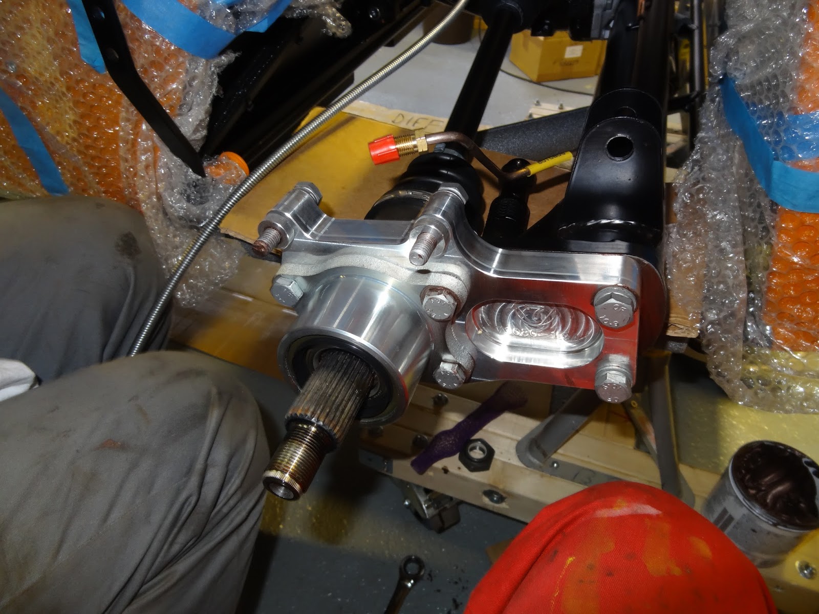
We dry fitted the ears, calliper brackets, and callipers to the De Dion tube in order to rivet the brake lines to the tube. Naturally we have found, as all others have, that the RH brake line requires bending to the correct angle to be able to be screwed into the back of the calliper.
It gets quite Confusing while trying to fit the right bolts in especially with the several varying lengths of M10 bolt in the pack, but we believe we have used the correct bolts.
LH Brake pipe with sleeve against watts-link/ radius arm bracket.
After bending the pipe we put the 5 P clips on the pipes then proceeded to rivet the pipes, only to find that the holes aren't quite large enough, so we quickly cleaned out the holes with a drill then properly riveted the hose on.
Hose sufficiently bent around 22mm socket set in the vice.
Having read through the manual for the correct procedure for putting the rear suspension in we realised that we needed to fit the roll bar as we had the new FIA variant meaning that it had to be fitted before the rear dampers, and that we perceived that it would be a shorter job than it would soon turn out to be...
FIA Roll Bar
This has probably been easily the second most, after generally having so many missing parts, that we have come across so far. Firstly having placed the bar onto the car and into the bucket bushes it was evident that the bar wasn't going to go in without a struggle. First of all the capheads passing up through the body and into the bottom of the bar went in ok, however it was evident that the top bolt passing in through the top wasn't going to align with the hole without a shove.
Top bolt hole.
To get these bolts in the struts must be pulled out and then pushed into the brackets in the rear of the boot, then while one person pulls the main hoop over to clear the hole the bolt can be tightened. However then the rear struts fall out. Anyway in the end we managed to break the head off of top bolt meaning the thing had to come off again. First we tried using mole grips to unscrew it without effect, meaning we were faced with having to drill the thing out... As one would tap a hole we increasingly drilled the centre out and eventually managed to remove enough material to be able to rip out the remaining threads and clean it out using a tap.
Bolt mid removal.
However eventually we were able to repeat the fitting procedure, taking even more care not to strip any threads, and got the thing in and torqued up.
Finally starting to look a little bit like the finished product.
Next time we will move onto the rear axle now that the roll over bar is in.