Friday, 13 November 2015

Build Day 16- 'A' Frame and Rear Dampers

Day 16- 'A' Frame and Rear Dampers


'A' Frame


We went out first and aligned the A frame and torqued it as required. The alignment was 3.5mm to the RHS off centre, with the advised 4 washers on the right and 3 washers on the left. We removed one large washer from the LHS then added a thinner heavy duty washer from each side. Then Torqued the frame and measured it again, which brought it within 1mm of centre (well at least was to the best of our abilities to accurately measure the alignment...).

Rear Dampers

We then moved onto the rear dampers which, as many other things, took longer than expected. The fit for the top bush was very tight, sufficiently enough for several whacks with a rubber mallet to not budge it an inch. Instead we used a fairly long, thin piece of hard wood, and a lump hammer in order to coax it in. Then end was placed on the edge of the bush and "persuaded" into place.    

Damper finally in place.
Here the calliper wasn't in place as the hub nut needed to be tightened for the disk to not foul on the calliper bracket. So after the dampers went in we fitted the calliper properly.

Bush in place with caphead in place.

New socket adapters. Bottom right (1/2" F to 3/4" M) used in 41mm socket.


Wednesday, 11 November 2015

Build Day 15- 'A' Frame, Steering, Rear Brakes

Day 15- 'A' Frame, Steering and Rear Brakes


'A' Frame

More prep for the weekend, so started with the A frame. I didn't want to fully fit it until dad got to have a say on it so I just loosely fitted it with roughly the right washers, the correct bolts in the front two mounts, and the correct bolt and nylon washers through the di dion tube. Just remember to tighten the A frame to the di dion tube before trying to centralise the A frame using the di dion tube, otherwise it will throw the tube out of alignment.

Rear A frame mounting with nylon washers, torqued first.

Rear Callipers and Brakes


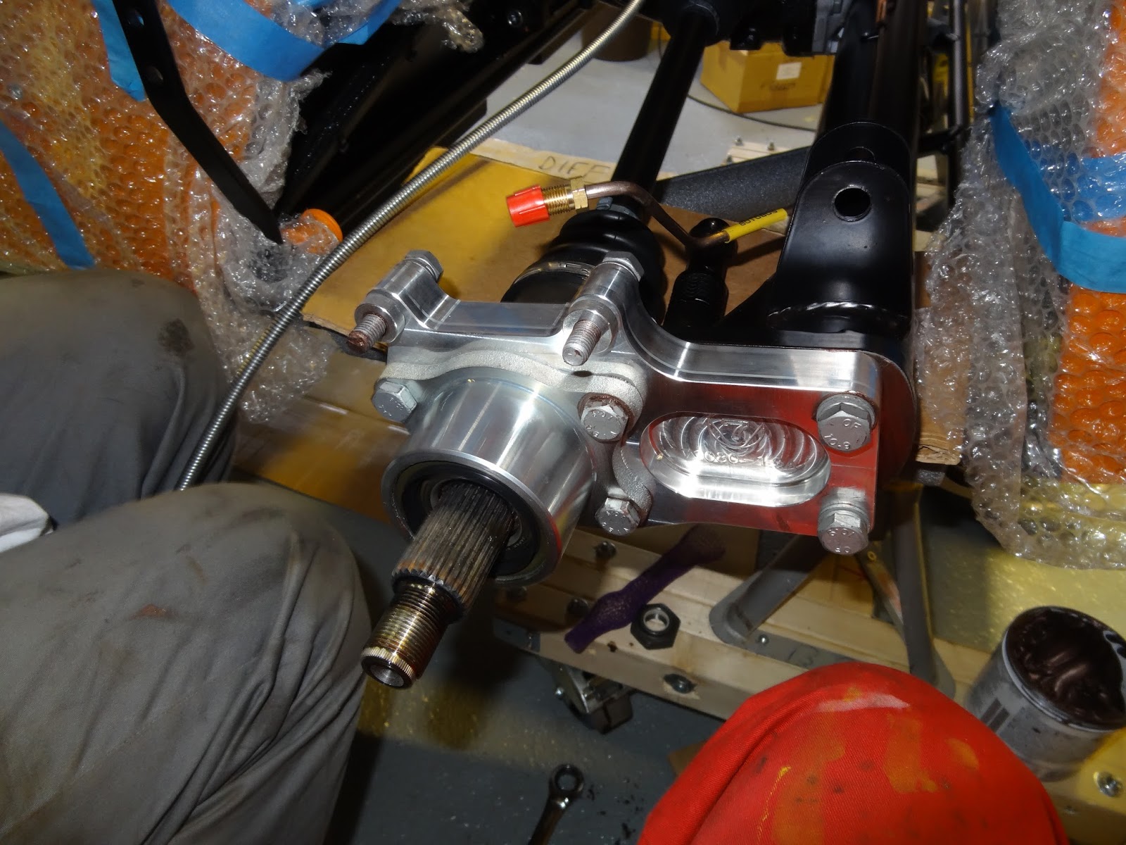
I then moved onto the rear calliper assembly. Firstly by sliding the disk over the splined end of the drive shaft, then putting the hub nut back. Following this the calliper brackets can be bolted onto the tube ears using the bolts used previously. The brake pads are then placed into the recessed slots either side of the calliper brackets. 

Before the callipers are bolted on the retaining clip must be slotted into the rectangular hole in the top of the calliper. We had found that attaching the brake line first to get the right alignment for the thread, then lowering the calliper into position and bolting it on, was the best way to fit the calliper, otherwise the brake line seems too easy to cross thread and it would be hard to get the perfect bend on the brake hose otherwise. 

Fitted calipers with clip in top.
I did also come to the conclusion that the disk would fit better once the hub nut had been tightened. I couldn't do this as the 41mm socket dad used on his previous Caterham had been rendered useless, as we have lost the 3/4" adapter required for the larger socket. We are just waiting for the new adapter set we have ordered.

Steering


The steering was fairly easy to put in, but couldn't be finished as we haven't finished cleaning and polishing the primaries, the cat, and the exhaust. The lower column went in first, just slid up through the two rubber grommets in the foot box, which was made easier by removing the covering plate. Then the upper column is slid down through, from the top, making sure not to dislodge the white plastic liner of the rubber bushes. The upper bush can be slid onto the upper column before or after, depending if a QR steering wheel has be opted for. 


Column clamp left loose for completion later.

I then loosely fitted the clamp to the middle of the column where the two meet, with the edges aligned. Moving onto the universal joint, between the steering rack and the steering column, it was evident that the job wasn't going to be completed due also to the front uprights looking considerably toe out, meaning that the track rod ends were going to have to be taken off and that the number if turns given in the instructions is wrong. I also found that the bolts passing through the universal joint and stopping it from pulling off wouldn't easily go through (only on the steering rack end) so the joint had to be opened up a little. 


Left like this until the primaries are fitted.

Later on we will finish this job once the exhaust is completed. This will hopefully resolve the wheel alignment (turns on the track rod ends) and also how much tilt is required on the steering rack, as we are unsure as to whether the steering column will foul on the primaries if the rack is at certain angles. We would prefer this to be as in line with the steering column as possible.


Tuesday, 10 November 2015

Build Day 14- Rear ARB, Rear End, and Handbrake

Day 14- Rear ARB, Rear Axle and Handbrake


Rear Anti-roll Bar


While dad was at work I decided to fit the rear anti roll bar, as it sounded as though it was either difficult to fit later or wouldn't go at all later on. Firstly the rubber bobbins went on easy enough with some silicone spray and some pulling, then I ignored the instructions about putting the bolts up through the chassis and bolted them down through so as to give an insurance measure in case the nylocs did work loose then the bolts wouldn't just fall out.


Parts required. Nice details on the ali mounts. 

Roll bar mounts fitted with bolts tightened down through the chassis.

Electronic gauge doesn't fit on the top so I calibrated one of the smaller torque wrenches.
In the end i couldn't finish the ARB fitment... this was due to the fact that we had not been supplied with the hexagonal spacer nut, which goes between the drop link and the de dion tube. 

(Turns out later on that Caterham do not do this anymore as the design has changed, so instead of the two drop link heads facing the same way, they face in opposite directions and bolt directly to the de dion mount and the ARB.) 

Propshaft


I then moved on to bolting the propshaft to the diff. Firstly I could only find 4, appropriately sized, cap heads not the bolts pictured. In order to stop the shaft from rotating I used to long screwdriver wrapped in a rag and inserted it through the universal joint. On my own it was only possible to get the screw driver through twice, on opposing sides, so I left the remaining two for when dad got home from work, so he could lock it from the top.

Shaft tied in place to stop scrapes appearing in the paintwork before the diff was installed. 

Screwdriver in place, more than enough to torque the bolts.

Hub Nuts


Yesterday we realised that the LH hub nut was too big to fit into the 41mm socket, so I filed down the edges of the nut until it fitted correctly.

Hub nut before.

Nut after.

Handbrake


When dad got home we got started together straight away, just to finish some bits and bobs. To start we fitted the handbrake, just a case of slotting it in, then through bolting the bracket. The bolts were a little tricky to get in as the brackets didn't align, but driving them through then tightening them pulled them into alignment.


A slight miss-alignment but went in after a little fiddling. 
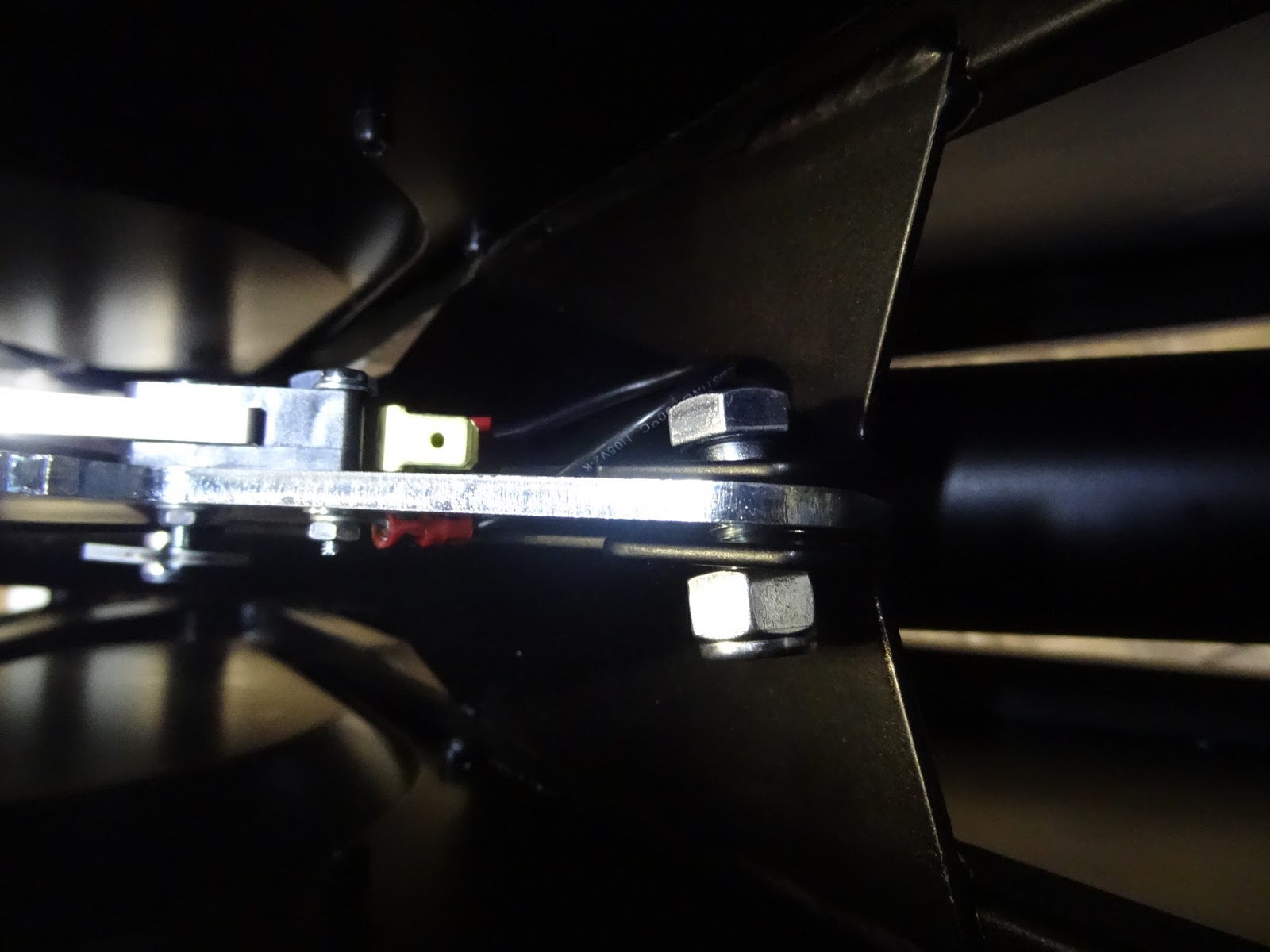
We then attached the pulley link to the brake cable. We found loosening the adjuster a foot or so allowed enough slack to work on the lever and pulley, and attaching the rear pulley first, before the front. The pins proved a little difficult as the holes aren't quite large enough, so they had to be persuaded through with some pliers.

Handbrake Cable with no twist (all SV cars).


Split pins in, a tad tricky as there is little room to move hands in the tunnel.
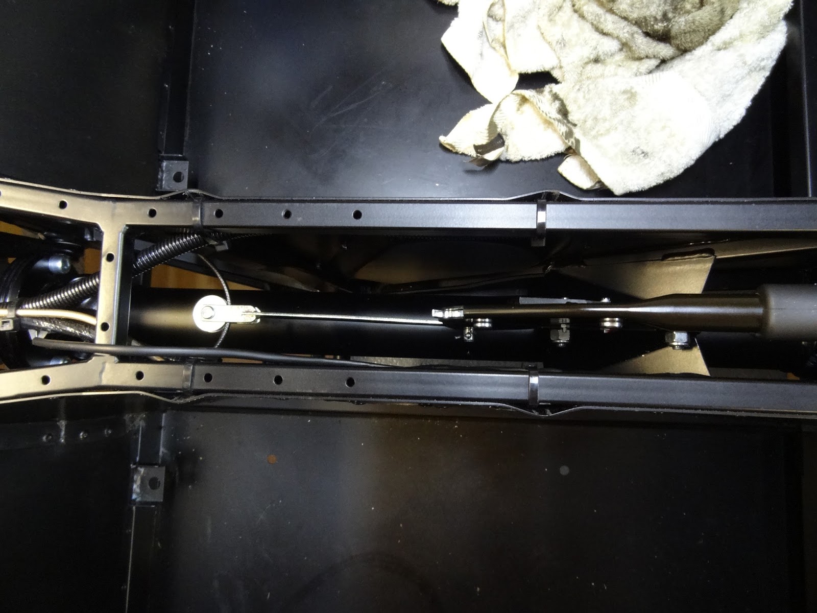
Overview of handbrake.

Torquing Ears and Bearings


We then moved onto the rear end, where we decided to torque up the aluminium ears and the bearings. This proved trickier than expected as there is limited access to the heads, mostly because we insist on properly torquing bolts by only torquing the nut and not the bolt, as the bolt will stretch if torqued much, even at low figures. In order to get to the heads and get enough leverage on the bolts we chocked up the de dion tube with a plank of wood. Also it was impossible to got the socket on the bolts around the RH drive shaft because of the speedo splines, so we had to wedge some wood in between the splines and the ears in order to torque the bolts.  

Making room around the drive shaft.

De Dion wedged up for torquing.

Monday, 9 November 2015

Build Day 13- Rear Axle and Limited Slip Differential

Day 13- Rear Axle and LSD


Preping LSD


We had originally decided to fill the diff off of the car and this may seem like an odd idea when looking at the diff upon arrival due to the dirty great hubs that have to be removed before inserting the drive shafts. 

HOWEVER there is no need to fill the diff after it is fitted!!!
And the same goes for the Gearbox, fill both before getting them in the car... no faff required!!! 

This is because the filler plug is below if not in line with the bottom level of the hubs. This seems to cause people trouble if they have either forgotten to fill the diff after the boot is finished or don't have decent way to fill the diff due to the limited space and awkwardness of its position. 

May have to admit though that we did fill the diff along with the gearbox, so technically we didn't realise the lack of need to fill after installation.

On another note we have done some research on running in etc which currently is pointing towards carrying out a full wet pack replacement after 10 or so miles so as to replace diff and gearbox oil. This is in order to remove material present after the mechanical parts are seated and worn in properly. The problem however is that it is then very hard to remove the oil from the diff without either removing the back plate or pumping it out. We will however endeavour to keep the blog up to date with our research, or if anyone has a strong opinion on the matter, then please feel free to comment below.

The hubs came off pretty easily, just a crowbar with the right leverage and then pop out quite easily.

Seats well under the flange.

Dad applying copper slip to the ends of the drive shafts, gestures unintended... just a side effect of the missing index syndrome...

Rear Axle


After putting the shafts in we removed all of the parts from the end of the de dion in order to get it passed the diff, which, at the moment, looks like it will have little or no room. However care and two sets of hands made light work of the job, which was completed by reassembling  the ears and bearings.

Ears and bearings fitted, with bolts copper slipped and tightened, not torqued.

Just checking the accuracy of a couple of our mechanical torque wrenches using the electronic one. The smaller one was only a couple of Nm out, however the largest one was more than 10Nm out, more than enough to strip a thread, which could cause catastrophic in the wrong place.

Now our shelved have a couple of lovely ornaments...

Saturday, 7 November 2015

Build Day 12- Rear Axle and Roll Bar

Day 12- Rear Axle and Roll Bar


Now the diff and the propshaft is in we can progress onto the rear axle. Yesterday evening we took a couple of hours to plan this morning and properly get to grips with the instructions, and get a little start on the De Dion tube by dry bolting the aluminium ears. Tonight we moved onto preparing the tube, and the car for fully fitting the rear suspension and axle.

De Dion Tube


We dry fitted the ears, calliper brackets, and callipers to the De Dion tube in order to rivet the brake lines to the tube. Naturally we have found, as all others have, that the RH brake line requires bending to the correct angle to be able to be screwed into the back of the calliper. 

It gets quite Confusing while trying to fit the right bolts in especially with the several varying lengths of M10 bolt in the pack, but we believe we have used the correct bolts.

LH Brake pipe with sleeve against watts-link/ radius arm bracket.
After bending the pipe we put the 5 P clips on the pipes then proceeded to rivet the pipes, only to find that the holes aren't quite large enough, so we quickly cleaned out the holes with a drill then properly riveted the hose on. 

Hose sufficiently bent around 22mm socket set in the vice.

Having read through the manual for the correct procedure for putting the rear suspension in we realised that we needed to fit the roll bar as we had the new FIA variant meaning that it had to be fitted before the rear dampers, and that we perceived that it would be a shorter job than it would soon turn out to be...

FIA Roll Bar


This has probably been easily the second most, after generally having so many missing parts, that we have come across so far. Firstly having placed the bar onto the car and into the bucket bushes it was evident that the bar wasn't going to go in without a struggle. First of all the capheads passing up through the body and into the bottom of the bar went in ok, however it was evident that the top bolt passing in through the top wasn't going to align with the hole without a shove. 

Top bolt hole. 
To get these bolts in the struts must be pulled out and then pushed into the brackets in the rear of the boot, then while one person pulls the main hoop over to clear the hole the bolt can be tightened. However then the rear struts fall out. Anyway in the end we managed to break the head off of top bolt meaning the thing had to come off again.

First we tried using mole grips to unscrew it without effect, meaning we were faced with having to drill the thing out... As one would tap a hole we increasingly drilled the centre out and eventually managed to remove enough material to be able to rip out the remaining threads and clean it out using a tap.  

Bolt mid removal.

However eventually we were able to repeat the fitting procedure, taking even more care not to strip any threads, and got the thing in and torqued up.


Finally starting to look a little bit like the finished product.
Next time we will move onto the rear axle now that the roll over bar is in.


Wednesday, 4 November 2015

Build Day 11- Propshaft and Diff

Day 11- Propshaft and Diff

Propshaft


Finally the right propshaft has arrived so we spent a few hours this evening putting it in and bolting in the diff. Firstly sliding in the propshaft took only a couple of minutes as it slides right in. If we had known how easy it was before then we wouldn't have spent so long trying to put the last one in.

Fits right in no trouble.

Limited Slip Differential


On the other hand the diff was slightly harder to fit due to the small amount room between the mounting bracket and the chassis. We lifted the diff with the trolley jack, which in the end wasn't quite tall enough to get it into place so the last centimetre had to be lifted into place by hand, then a long screwdriver was inserted to pin it in place.   

Using a tape covered file to lever the diff in order to get the washers in.
Initially we had a lot of trouble getting the bottom bolts in so we decided to put a chamfer on each end, like on the top bolt (already done by Caterham) in order to get the washers on then into the thread on the diff bracket. After this it was much easier to get the bolts in and done up. We then propped up the diff with an off cut of wood in order to bolt through the top. The top washers were much easier to place from above, through the boot floor with the wooden panel removed, using a screwdriver to get the washers aligned. (Edited by Dad, I think we should confess to having spent quite a lot more time on the bottom bolts than we should have, due to "us", (that's the royal version of me), using washers, a size smaller than the bolt!!!). 

Putting the chamfer on the bottom bolts using the bench grinder.

Two nuts retained on bolt in order to re shape the thread.


Tuesday, 3 November 2015

Build Day 10- New Toys and Cooling Hoses

Day 10- New Toys and Cooling Hoses 

Annoyingly we haven't had any time to do anything for a while and doesn't look great for the near future. However while at home I can still have a little fiddle so not a fully day today, just an hour while dad is at work, just to figure out what we are going to do next and to open a new toy which arrived this morning.

New Toys

Firstly unwrapping the trolley jack just to realise just how big it is...  

3 Ton, 98-535mm Trolley Jack, By SGS Engineering.

Now we "technically" are able to get the car off of the stands we have made...

Cooling Hoses

After playing around with the new Trolley Jack I went on to dry fit the cooling hoses, which, as usual was harder than planned due to the standard insufficient number of parts. However I was able to get one of the hoses into place and figure out where on of the others goes.

Bottom radiator hose passing along stearing rack.

Bottom radiator hose connecting to LHS of block.

Oil Breather pipe, has to be cut to fit to dry sump tank.

Having a look at the other three hoses it was clear that none of them were were going to fit. Pretty sure the 'J' hoses are heater hoses for connecting to the modine, which is useless for us as we have a dry sump system (Modine on wet sump engines only). Also the small 'L' hose is another oil breather pipe.


The other three hoses.

Supplied 'J' Hose ends are way too big to fit onto the end of the water outlets.

Went to offer up the throttle cable as it looked quite short to say the least, only to find it barely stretches the width of the car.

This is how I Believe the car should be plumbed, however if it changes don't be surprised as it'll be due to the confusing manual having detailed instructions for Duratec engines and a couple of sentences and a picture for the dry sump version. (Image styled heavily on Tom's on his Supersport R Blog)
So to sum up we'll have to send an email to Caterham to get the required heater hoses (orange and red), the water expansion hose (Purple) and to get the right throttle cable.